
Solar energy is the most abundant and renewable source of energy available on the earth. To utilize this energy, various types of technologies are used that converts solar energy into heat and electricity. The use of solar cells or photovoltaic cells (PV) is one of the most prominent and widely used methods to utilize solar energy. Solar cells are the electronic components that produce electricity when exposed to sunlight using the photovoltaic effect. The phenomenon of the generation of electric current or voltage in a circuit when it is exposed to light is known as the photovoltaic effect. This effect was discovered by a French physicist ‘Alexander Edmond Becquerel’ in 1839. Later, in 1883, Charles Fritts, a New York inventor, constructed the first solar cell, which was made of selenium with the coating of a thin gold layer. In the 1960s, solar cells were primarily used in satellite technology and by the end of the 1980s, solar cells also begin to use on the rooftops of the buildings. Afterwards, the use of solar cells for the generation of electricity for domestic and industrial purposes is significantly growing day by day.
Construction of Solar Cell
A solar cell is a p-n junction diode, but its construction is slightly different from the normal junction diodes. Some specific materials, which have certain properties such as bandgap ranging from 1 EV to 1.8 EV, high electrical conductivity, and high optical absorption, are required for the construction of solar cells. Semiconductors such as Silicon, Gallium Arsenide, Copper Indium Selenide, Indium Phosphide, and Cadmium Telluride satisfies these conditions; hence they are generally used for constructing solar cells. Semiconductors can absorb the EM radiations of the wavelength equal to the visible light (400-700 nm), which increases the efficiency of the solar cells. Solar cells consist of an optical coating at the top, which is called the antireflection layer. The antireflection layer is typically made of oxides of Titanium, Tantalum, or Silicon through the vacuum deposition process or spin coating. This layer traps most of the sunlight falling upon it and transmits it to the three energy-conversion layers, i.e., the top junction layer, the absorber layer, and the back junction layer; all these layers lies below the top anti-reflection layer. Two more electrical contact layers are coated at the top and back of the circuit that carries the current to the output terminal and then back to the solar cell and complete the electric circuit. The top layer is made up of good electricity conducting material, which is generally a metal having a grid pattern with thin and widely spaced grid lines to allow the maximum light collection as a thick metal layer can block the sunlight. However, the back layer does not have such a problem, so it is simply a plane coating of the metallic layer. The solar cells consist of a thin layer of p-type material coated over the comparatively thicker layer of n-type material. A few thin electrodes are applied over the p-type layer, and some electrodes are applied at the bottom of the n-type region to collect the electric current. This entire setup is then encapsulated in a thin glass that protects the sensitive components of the solar cell from dirt, extreme weather conditions, and any mechanical shocks.

Construction of a Solar Cell
Working Principle of Solar Cell
Solar cells work on the principle of the junction effect in the P-N junction diodes. Let us first discuss the p-type and n-type materials to understand the junction effect. The p-type and n-type materials are the semiconductors, say silicon or germanium, which consists of some atomic impurities, and the type of semiconductor (either p-type or n-type) depends upon the type of impurity added to them. The process of adding impurities to the semiconductor is known as dopping.
P-type Semiconductor: Let’s consider an example of a pure silicon crystal. Each silicon crystal consists of four valence band electrons, which are bonded with its neighbour silicon atom through four covalent bonds. The pure silicon crystal structure is properly aligned as there is no extra electron or hole in it. Now, let us assume that one silicon atom of the crystal is replaced by another atom, say Boron. The Boron atom consists of three valance band electrons. When we dope the silicon crystal with the boron atom, the three bonds of the silicon atom will make the bond with the three valence bands of the boron; however, one electron of the silicon atom will remain unbonded due to the unavailability of the 4th valence electron in the boron, which leaves an excess hole in the lattice. The semiconductors that consist of more holes than the electrons in the crystal lattice are known as the P-type semiconductors, where p stands for positive. Hence, in p-type semiconductors, the flow of electric current is largely due to the holes as the electrons act as the minority charge carriers, while the holes act as the majority charge carriers.

N-type Semiconductor: Now let’s assume that the pure silicon crystal is doped with the phosphorus atom instead of the boron. The phosphorus atom consists of five valence electrons. When the phosphorous atom is doped in the silicon lattice, the four valence electrons of the phosphorous atom will bond with the four valence electron of the neighbour silicon atom; however, the 5th valence electron of the phosphorus remains unbonded. This extra electron can leave the phosphorus atom even on the application of slight thermal energy. Hence, due to the presence of more electrons than the holes, these types of semiconductors are known as the N-type semiconductors, where N stands for negative. Here, the electrons are the majority charge carriers, and the holes are the minority charge carriers. Unlike p-type semiconductors, n-type semiconductors can donate electrons.

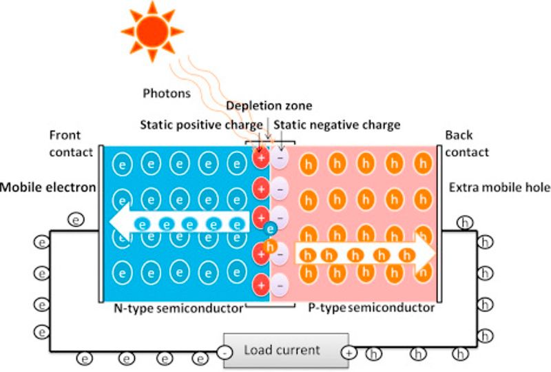
The solar cells are constructed by joining the layers of the two types of semiconductors, i.e., n-type and p-type, with each other, where one layer is capable of donating electrons (n-type), and the other layer is capable of accepting electrons (p-type). The n-type layer is heavily doped, i.e., have a large number of electrons and is usually kept thin to ensure that sunlight can easily pass through it to the lower layers. Whereas, the p-type layer is lightly doped to ensure that most of the depletion region forms on the p side. When both the p-type and n-type layers are joined together, then the electrons from the n-type layer starts moving towards the holes in the p-type region near the junction. This creates an area called the depletion region around the junction where the electrons fill the holes. When each hole in the depletion region is filled with electrons, the p-type region now has negatively charged ions, where holes were present initially, and the n-type region has positively charged ions, which has electrons initially due to the built-in electric field and induced potential difference across the junction.

The representation of the P-N Junction effect in a solar cell.
Due to the presence of oppositely charged ions, an internal electric field is built in between the depletion layer, which prevents the electron in the n-region to recombine with the holes in the p region. When the sunlight falls on the surface of solar cells, it absorbs some photons, and some of these absorbed photons, which have more energy than that of the energy bandgap (the gap between the conduction band and the valence band of the semiconductors crystal used in the construction of solar cells) will be able to eject out the electrons from the bond, which results in the formation of electron-hole pairs, these are known as the light generated electron-hole pair. If the electrons are ejected from the depletion layer, the electric field will force the electrons to move in the n-type region and holes to the p-type layer. If we connect an external load, the electrons from the n-type region will travel to the p-type region through the depletion region and then passes through the external wires connected at the back of the n-type layer, hence the flow of electricity begins.
Working of a Solar Cell
Parameters of Solar Cell
The efficiency of the solar cells, i.e., the ability to generate electricity from sunlight, is determined by the different parameters of the solar cells. Let us understand these parameters of the solar cells.
1. Short Circuit Current of Solar Cell (Isc)
It is the maximum current that a solar cell can produce without any failure. The value of this current is measured by short-circuiting the cell terminals at the most effective solar cell condition for maximum efficiency. The most effective condition is referred to here as maximum light intensity and the appropriate angle of the cell when sunlight falls on its surface because the electricity generation rate by the solar cells depends upon all these factors. As the production of electricity also depends upon the solar radiation falling on the surface of solar cells, cell area, and angle of solar cells, hence some manufactures use the term current density instead of the current value. The current density is represented by the letter “J” and the short circuit current density is represented by the “Jsc”. The short circuit current density is the ratio of the short circuit current (Isc) to the area of the solar cell (A). Mathematically, it is represented by,
Jsc=Isc/A

The representation of the short circuit current of a solar cell.
2. Open Circuit Voltage of Solar Cell (V0c)
When no load is connected to the solar cells, then the voltage that is measured across the terminals of the solar cells is known as the open-circuit voltage of solar cells. The open-circuit voltage depends on manufacturing technique and temperature; it usually ranges from 0.5 to 0.6 volts.

The representation of open-circuit voltage of the solar cells.
3. Maximum Power Point of Solar Cell (Pmax)
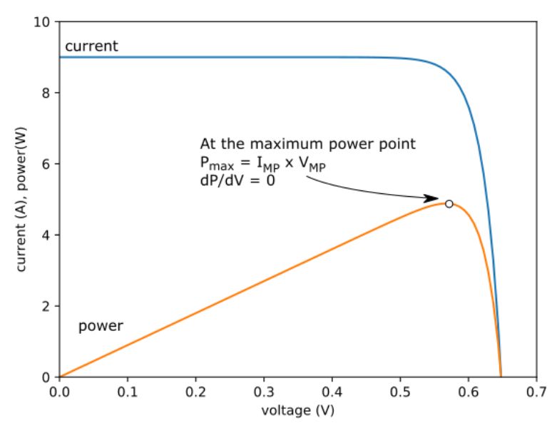
A solar cell can work at different voltages and current combinations, but it generates maximum power only at certain values of current and voltage combinations. The maximum point of a solar cell is the maximum electric power that can be generated by it at some particular standard conditions. Usually, the maximum power is measured at the 1000 W/{m}^{2} solar radiance and {25}^{0}C cell operating temperature. If we draw the VI characteristics of the solar cell, the maximum power point of solar cells can be observed at the bending point of the V-I curve (as shown in the fig. below).

The representation of ‘maximum power point’ of the Solar Cells.
4. Current at Maximum Power-Point (Imp)
It is the current generated by the solar cell when it is working at the maximum PowerPoint. Its values always remain less than the short circuit current, and it is measured in milli-ampere (mA) or ampere (A).
5. The voltage at Maximum Power-Point (Vmp)
It is the voltage produced by the solar cell when it is working at the maximum PowerPoint. It is measured in millivolts (mV) or Volts (V). The value of the open voltage current is always greater than the value of the voltage at the maximum power point.
The representation of the ‘Voltage at Maximum Power-Point’ of the solar cells.
6. Fill Factor of Solar Cell (FF)
In V-I characteristics of the solar cells, the fill factor is represented by the total area covered by the current at the maximum power point and the voltage at the maximum PowerPoint (Imp-Vmp) rectangle with the total area covered by the short circuit current and open-circuit voltage (Isc-Voc) rectangle, as shown in the image below. Mathematically, it is the ratio of the product of the voltage and the current at the maximum power point (Vmp×Imp) to the product of open-circuit voltage and the short circuit voltage of the solar cell (Voc×Isc), i.e., the maximum power divided by the theoretical power.
It is expressed as
Fill Factor (FF) = Pmax/Pth = (Imp×Vmp)/(Isc×Voc)
Where Pmax is the maximum power, and Pth is the theoretical power.
The higher the fill factor means the higher the efficiency of the solar cell, and the VI characteristics curve will become more ideal, i.e., square. The fill factor is usually measured in terms of percentages, hence, the above formula is multiplied by 100, i.e., FF% =(Pmax/Pth)100. The higher the percentage obtained the higher will be the efficiency of the solar cell. For silicon solar cells, the fill factor percentage is near 80%.

The V-I representation of the ‘Fill Factor’ of the Solar Cells.
7. The Efficiency of Solar Cells (η)
The efficiency of the solar cell is the ratio of the maximum output power to the input power (input radiations). It is represented in terms of percentage. The total radiation power on the earth is considered about 1000 watts per square. Hence, if the total surface area of a solar cell that is exposed to the radiations is A, then the total solar radiations falling on the surface of the solar cells will be 1000 watts. Therefore, the efficiency of the solar cells is given by,
η=Pm/Pin ≈ Pm/1000A
Where η is the efficiency of the solar cell, Pm is the maximum output power, and Pin is the total input power.
Main Components of Solar Power Plant
1. Solar Panels
The current obtained from the single solar cell is very low having an output voltage of around 0.6V. Hence, many solar cells are arranged together in different combinations to increase the output voltage or current. This combination of solar cells forms the solar pannels. Let’s discuss the three ways of arrangement of solar cells.
Series Combination of Solar Cells: If two or more solar cells are connected with each other in series, the input voltage will become double, while the output current remains the same.
Parallel Combination of Solar Cells: If solar cells are connected in parallel, the output electric current becomes double, and the voltage remains the same.
Series-Parallel Combination of Solar Cells: When the solar cells are connected in the series-parallel combination, the value of both the electric current and voltage increases. Hence, a series-parallel combination is used for the construction of solar panels. By connecting various single solar cells, a solar module is constructed, and these solar modules are further joined to form solar arrays.

2. Maximum Power-Point Tracker
These are the special digital trackers that are installed in the solar panels to follow the maximum sunlight direction. The efficiency of the solar cells depends on the amount of sunlight falling over the surface of solar cells. The intensity of the sunlight in a particular direction varies along with time due to the movement of the earth, hence, the solar panels also need to shift direction towards the direction of the maximum sunlight intensity. This is done with the help of the maximum power point trackers.

3. Solar Charge Controller
The charge controller manages the total voltage obtained from the solar arrays to the battery bank. They are used to ensure that the batteries won’t get overcharged during the peak hours of sunlight, i.e., daytime, and also they won’t get drained due to the backward flow of the power from the batteries to the solar cells during the off-hours, i.e., during the night hours. Hence, the primary function of the charge controller is to protect the battery, but some advanced solar charge controllers also have the ability to control the load and the light intensity.
4. Inverters
It is one of the most important parts of the solar energy system as it makes the electric current obtained by the solar cells be used for domestic or industrial purposes by converting it into the direct current (DC) from the alternating current (AC). They also monitor the performance of the solar plant and provide the necessary data, which can help in diagnosing any technical issues in the solar system. Apart from it, inverters also help in storing the extra energy generated during the daytime into the batteries that can be used at the night.
5. Solar Racking
This is also referred to as the photovoltaic mounting system. It is a special system that is designed to safely install solar panels at various locations such as the roof of the buildings or grounds.
Factors affecting the Power Produced by the Solar Panels
1. Input Light
The amount of electric current produced by solar power is directly proportional to the amount of light falling on its surface, i.e., the more the amount of light falling on the solar cells more will be the electricity generated. As the amount of sunlight falling on the solar cells changes throughout the day, so does the voltage and current produced by the solar cell also changes. In the peak sunlight hours, the light falling on the solar cells is maximum, hence, solar cells generate maximum current during this period, while the power produced is minimum during the off-peak hours of sunlight.
2. Efficiency (η)
The solar cell does not convert all the light that strikes its surface into electricity. It depends upon the efficiency of the solar cells. The efficiency of the solar cell depends upon the material used and the manufacturing process, hence the efficiency value remains the same and can’t be varied, although it may reduce due to certain factors. The maximum power (Pm) produced by the solar cells is given by,
Pm=(Pin)(A)(η)
Where P is the input power, A is the area of the solar cells, and η is the Efficiency of the solar cells.
3. The angle of incidence of light (θ)
It is observed that when the incident light strikes at an angle of 90 degrees with the surface of the solar cell, maximum power is produced by the solar cells, while if the angle of incidence is less than or more than the 90 degrees, the solar cells generated the less power than that of its capability of generating maximum output power. It happens because when the light falls at any other angle than 90 degrees, some part of the incident light gets reflected, hence the light absorbed by the solar cells is lesser than the light falling on its surface, which eventually results in the low output power. Hence, the solar panels are carefully fixed in the direction perpendicular to the direction of the incident light.
4. Area of the Cell (A)
Like input light, the area of the solar cell is also directly proportional to the electric current produced by the solar cell, i.e., if the solar cells have a larger surface area, the amount of electricity generated by them is also larger.
As we have discussed earlier, the current density of the solar cells is given by,
Jsc=Isc/A
Where Isc is the short circuit current, Jsc is the current density, and A is the area of the solar cells.
Therefore, Isc =Jsc*A
Hence, it is clear from this expression that the area of the solar cell and the short circuit current are directly proportional.
5. Operating Temperature (To)
The current and voltage generated by the solar cells as provided by manufacturers are according to the standard testing conditions (STC) such as 1000 watts per square and 25 degrees Celsius temperature. However, practically, the operating temperature of the solar cells does not remain the same as per the STC due to the extremely sunny days, and the solar cell is encapsulated in the glass, which may further increase the temperature. The rise in the temperature above the standard conditions may reduce the output power of the solar cells, hence directly affecting the efficiency of the solar cells. For example, consider a solar cell having an output voltage of 0.6 V at the standard testing conditions (Tstc= {25}^{0} C) as mentioned by the manufacturer. However, it is observed that the actual voltage of the solar cell is decreased by 1.8 mV per degrees Celsius at its operating temperature (To) of 50 degrees. Hence,
The change in temperature (ΔT) = To – Tstc= 50 – 25= 25 degrees
The actual output voltage at the operating temperature will be,
Voltage at STC – (Decrease in Voltage × ΔT) = 0.6- (1.8 × {10}^{-3} × 25)= 0.6- 0.045 = 0.5 V
So, it is clear that if the temperature increases more than the STC, the output voltage of the solar cell decreases.
Advantages of Solar Cell

- The prominent advantage of the energy generated by solar cells is that solar energy is a renewable source of energy. Any kind of natural fuels such as coal and petroleum are not consumed during this process. Solar energy is available in all parts of the world, and that too is in abundance. It can be utilized as much as we need because we are not running out of this energy as long as the sun is available to us.
- Solar cells, once installed, requires very less maintenance cost as they are strongly built to withstand any mechanical shocks or extreme weather conditions. The solar panels often come with a minimum guarantee of 20 years.
- Solar cells do not release any dangerous water or air toxicants that may affect the environment; instead, they are used to reduce climatic changes by replacing the other means of electricity generation that releases harmful emissions. Another advantage is that solar cells are that they do not have any moving components, hence they do not create any noise while generating electricity.
- Solar cells are highly economical, you need not pay the bill for consumption of the electricity you generates through your solar panels. Moreover, you can monetize the electricity generated from your solar cells if your solar system is connected to the grid, by selling electricity to the electricity network.
Disadvantages of Solar Cell

- The location where the solar cells are to be installed plays a crucial role. One can not get the optimum power from the solar cells if the sunlight does not directly fall on them at an optimum angle, or if there remains shade on the solar cells for most of the time, hence solar cells demand an appropriate installation location to generate electricity. Moreover, the energy cannot be produced during the cloudy days and night periods due to the unavailability of sunlight, hence solar cells can not produce electricity 24/7.
- As compared to other renewable methods of electricity generation, solar energy is highly affected by seasonal changes. During the cold seasons, the power obtained by the solar cells is less as compared to the hot seasons due to shorter days and longer nights, or other atmospheric conditions such as snow may cover the solar panels. According to a study conducted in India, it is observed that the electricity obtained by the solar cells in the extreme colder months (December and January) is around 40-60% less than the electricity obtained in the extreme summer months (July and August).
- People usually hesitate to choose solar cells for electricity generation due to their high installation cost. The inefficient instalment of solar panels on the roofs can also be a problem; however, the government encourages people to install solar panels on the roofs of their houses, and most of the banks also provide loans and low-interest schemes to the customers who invest in solar cells.