
In our daily lives, we come across a variety of battery-powered electrical gadgets that transform electrical energy into mechanical energy, such as hairdryers, toy vehicles, tiny fans, trimmers, and so on. The electrical component responsible for this action is a Direct Current (DC) motor present inside those gadgets. A DC motor is a device that works on direct current and converts it into mechanical work. The official credit of inventing the DC motor goes to an American blacksmith, Thomas Davenport; however, several other scientists, including William Sturgeon and Frank Julian Sprague, have also contributed to the development of the DC motor. Today, DC motors have become an integral part of the industrial sector and are used for various applications, such as electric vehicle propulsion, elevators, cranes, and steel rolling mill drives. To understand how a DC motor works, let’s first look at the components used in its construction.
Components of a DC Motor
A DC motor usually looks like a cylindrical device with a shaft extending out of it that rotates on applying DC. This action is carried out by arranging the following components in a particular manner.
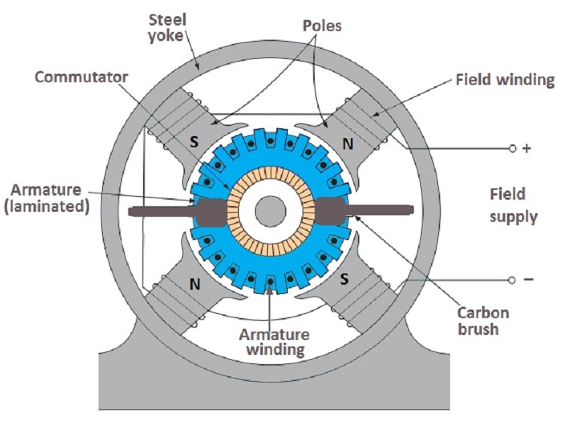
Stator
A stator, or a steel yoke, is a cylindrical metal casing inside which all the other elements of a DC motor are placed. One face of the stator contains a vertical shaft coming out of it, while the other face has the two terminals to which the DC power supply is connected.
Magnets
There are two stationary permanent magnets installed inside the stator of a DC motor. They act as the north and south poles of a magnet by setting up a horizontal magnetic field across them.
Armature
In electrical engineering, the term armature refers to a structure of rotating coils under the influence of electromagnetic force. In a DC motor, an armature is composed of a rotor placed between the two magnets. A rotor is a structure of laminated discs wrapped around by a conducting field coil. The shaft pointing out of the motor passes along the axis of the armature and rotates along with it.
Field Coil
The field coil or field winding in a DC motor is a coil of copper wires that replaces the permanent magnets attached to the inside walls of the stator. When DC from a battery is passed through this coil, it forms an electromagnet whose polarity can be controlled, setting up a desired magnetic field.
Commutator
A commutator is a hollow cylindrical piece segmented at many spots to reverse the polarity of the electromagnetic armature coil inside the DC motor. It is a critical part of a motor to work on a DC power supply. It sits at the end of the armature around the shaft. The ends of the armature coil are connected to the commutator, while all other parts, except brushes, are electrically isolated from it.
Brushes
The brushes in a DC motor are the components that connect the static terminals to the rotating parts of the motor. They are usually made of carbon graphite since it is a great conductor of electricity and have excellent lubricant properties. The commutator is positioned between the two brushes, which are further connected to the motor’s terminals, completing the circuit with the DC power source.
Working Principle of a DC Motor
A DC motor works on the principle that whenever a current-carrying conductor is placed inside a magnetic field, it experiences a magnetic force whose direction is given by Fleming’s Left-hand Rule. In other words, the DC motor spins due to the interaction of the permanent magnet’s magnetic field with the magnetic field of the current-carrying electromagnet.

Fleming’s Left-hand Rule

Fleming’s Left-hand rule is a mnemonic tool to understand the mutually perpendicular relationship between the current, an applied magnetic field, and induced force in an electric motor. If we extend the index finger, middle finger, and the thumb of the left hand in mutually perpendicular directions, aligning the middle finger with the conventional direction of current inside the current and the index finger with the applied magnetic field, then the thumb gives the direction of the force experienced by the conductor. To understand how this acts inside a DC motor, let’s discuss the working of a DC motor in more detail.
Working of a DC Motor
To understand the working of the DC motor, let’s first take a simpler case of a single rectangular wire loop place inside the north and south poles of a permanent magnet. As the current flows through the wire loop, it creates a magnetic field around it that interacts with the pre-existing magnetic field of the permanent magnets, resulting in a repulsive force whose direction can be determined using Fleming’s left-hand rule. The direction of current for the wire segment near the north pole of the permanent magnet is forward (going away from the positive terminal of the battery), which causes the force to be directed downward. Similarly, for the wire section near the permanent magnet’s south pole, the current is flowing backward (towards the battery’s negative terminal), causing the force to be directed upwards. The two opposite directions of forces develop the torque in the coil, causing it to spin around the axis.

Nonetheless, a single loop of wire would not have enough magnetic strength to come over the magnetic flux of permanent magnets and will eventually stop, forming an equilibrium. The intensity of the electromagnet’s magnetic field is enhanced by coiling it around the limbs of the rotor. In a DC motor, the current enters the coil through a commutator that rubs against one of the brushes connected to the DC power supply. As the current moves through the coil, the rotor starts to rotate as the result of the torque acting on it. The segmentation of the commutator allows the armature to avoid the equilibrium position by cutting off some coils from the power supply and ensuring a unidirectional torque. This cycle repeats periodically, resulting in the rotation of the shaft attached to the armature.
Types of DC Motor
Direct current (DC) motors are ubiquitous in today’s industrial sector and serve various small and medium-sized motoring applications, ranging from robotics to transportation. Because of their versatile functionality, there are several types of DC motors available in the market which can be categorized based on their connections as follow:
Permanent Magnet DC Motor
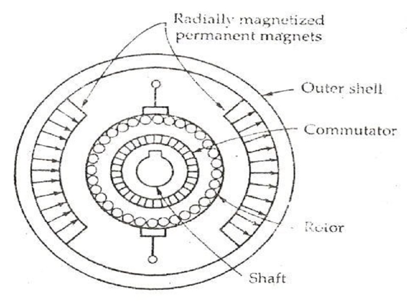
A permanent magnet DC motor is a typical example of a DC motor in which permanent magnets provide the crossectional magnetic field inside the stator. A pair (or pairs) of radially magnetized permanent magnets are fixed to the inside walls of the stator, with the north and south poles alternatively facing each other and producing a uniform magnetic field between them. In addition to holding the permanent magnets, the cylindrical shape of the steel stator also serves as a low-reluctance return channel to the magnetic flux. The disadvantage to these types of DC motors is that the permanent magnets can lose their magnetic properties over time; however, in some advanced permanent magnet DC motors, the magnets work in conjunction with additional field coils to compensate for lost magnetization.
Applications
Permanent magnet DC motors are typically found in those electrical devices that do not consume much power and do not require very effective control over the speed of the motor. Few examples of such electrical devices are toy cars, wipers, hot air blowers, compact disc drives, etc.
Separately Excited DC Motor

An excited DC motor contains an electromagnetic field coil instead of permanent magnets to set up the magnetic field inside the stator. These motors have a field excitation arrangement installed inside the motor that generates the magnetic field employing an electric current. In a separately excited DC motor, the circuit providing the current to field excitation arrangement has a different voltage source from the one that supplies current to armature coils. In other words, the current that flows through the armature coils does not flow through the coils of field excitation arrangements. The field excitation arrangement works on a constant voltage, whereas the armature coils can have variable voltage to adjust the speed of the motor. Furthermore, by switching the polarity of the field coils, the rotational direction of the motor’s shaft can be instantly flipped. Nonetheless, there is a disadvantage of the additional voltage source cost required to excite the field coil.
Applications
Separately excited DC motors are commonly encountered in electrical appliances that require rotation in both directions with accurate speed control. They are employed in various appliances, including paper rolling machines, electric propulsion ships, and even traction controllers in electric trains.
Self-Excited DC Motors
As the name suggests, self-excited DC motors are those which have a common source of voltage for field coils and armature coils. Both the coils can be connected either in series or parallel, or some combination of series-parallel configuration. Based on their connection configuration, self-excited DC motors are further classified into three categories as follow:
Series-Wound Self-Excited DC Motor

In a series wound self-excited DC motor, the field coil is connected internally in series with the armature coil. Although the structure of the series wound self-excited dc motor is similar to other excited DC motors, the field coil of a self-excited dc motor contains relatively fewer turns and has a thicker wire than the armature coil, ensuring a low electrical resistance. As a result, the electromagnetic torque generated in this case is far higher than usual, resulting in a faster motor speed. Nonetheless, the speed control in series-wound self-excited motors is not as impressive as other excited motors.
Applications
Due to their fast speed, series wound self-excited motors are commonly employed as starter motors for heavy-duty industrial appliances such as cranes and lifts. Furthermore, series motors are often only utilized for a short amount of time, such as a few seconds, because the high series current can burn out the series field coils, rendering the motor useless.
Shunt-Wound Self-Excited DC Motors

In a shunt-wound self-excited DC motor, the field coil is connected in parallel to the armature coil of the motor, resulting in similar voltage but a different amount and flow of current for both the coils. When compared to the armature winding of a DC motor, the field winding has a considerably higher number of turns to increase net flux connectivity and a smaller diameter conductor to increase resistance (lower current flow). This gives the shunt-wound self-excited DC motor a unique capacity to self-regulate its speed when a load is applied to the shaft of the rotor terminals. In other words, when the motor is switched from no load to loaded, the speed of the motor does not fluctuate significantly.
Applications
Shunt-wound self-excited DC motors are commonly encountered in appliances that run at a constant speed. Their self-regulating speed capability comes in handy where precise speed control is required, e.g., grinding machines, printing machines, lathes, etc. Nonetheless, the load during the initiation of the motor must be limited, as it cannot produce high starting torque.
Compound-Wound Self-Excited DC Motors

A compound-wound self-excited DC motor, also known as a DC compound motor, is a combination of both series and shunt-wound motors. In DC compound motors, the field coils are connected in both series and parallel configurations to the armature coils. The goal of such a structural combination is to obtain the best qualities of both types. A shunt motor has a very efficient speed regulation, whereas a series motor has a very high beginning torque. As a result, a compound DC motor is a fantastic compromise in terms of these characteristics. Both the field coils work in conjunction to provide the required magnetic flux and desired speed of rotation. Based on its field coil connections with the armature coil, the compound wound DC motor can be further classified into two basic types:
- Long Shunt Compound Wound DC Motors are those in which the shunt-wound field coil is linked in parallel across the series combination of armature and field coil.
- Short Shunt Compound Wound DC Motors are those in which the current first passes through the series-wound field coil and then splits into a parallel connection of the shunt-wound field coil and the armature coil.
Moreover, DC compound motors can also be classified into two other categories based on excitation and characteristics of compounding:
- Cumulative Compounding: In a cumulatively compound DC motor, the shunt field flux created by the shunt field coil enhances the effect of the main field flux produced by the series field coil. In other words, the flux produced by the shunt coil winding adds up to the flux produced by the series coil winding to give the total flux.
- Differential Compounding: The motor is said to be differentially compounded if the shunt field flux reduces the impact of the main series winding. This happens because of the opposite polarities of the shunt wound field coil and the series wound field coil. Because the net flux created in this instance is lower than the original flux, this configuration is unlikely to be of any practical use.
Applications
Like Shunt-wound self-excited DC motors, a compound DC motor is also often found in the devices that require running at a fast and constant speed. The major difference in their utility is that DC compound motors can run irrespective of the load attached to the shaft. In other words, the load is not much of a concern in the case of DC compound motors. Common applications of compound wound DC motors can be seen in machines such as escalators, elevators, stamping presses, rolling mills, reciprocating machines, etc.
the notes are so helpful